Mechanical Drawing Lines Definition. This post discusses the advantages of using the bs & iso standard line type definitions. They convey critical information, dimensions, and details that guide the construction of complex structures, machinery, and systems. the most common is a continuous line, also known as a drawing line. They are fine, dark lines. Certain features on a engineering drawing requires specific ways of. the diagonal lines on the section drawing are used to indicate the area that has been theoretically cut. these lines are used to represent the outlines of adjacent parts, extreme positions of movable parts in the assembly drawings, parts. In this comprehensive guide, we’ll delve into the diverse world of lines used in engineering drawings. lines in engineering drawing are more than just strokes on paper; Various types of section lines may indicate the. lines on mechanical engineering drawings. / learn mechanical drawings / by piet. different line types used on engineering drawings. section lines are used to show the cut surfaces of an object in section views.
from www.youtube.com
They are fine, dark lines. This post discusses the advantages of using the bs & iso standard line type definitions. / learn mechanical drawings / by piet. They convey critical information, dimensions, and details that guide the construction of complex structures, machinery, and systems. the diagonal lines on the section drawing are used to indicate the area that has been theoretically cut. the most common is a continuous line, also known as a drawing line. these lines are used to represent the outlines of adjacent parts, extreme positions of movable parts in the assembly drawings, parts. different line types used on engineering drawings. lines on mechanical engineering drawings. Certain features on a engineering drawing requires specific ways of.
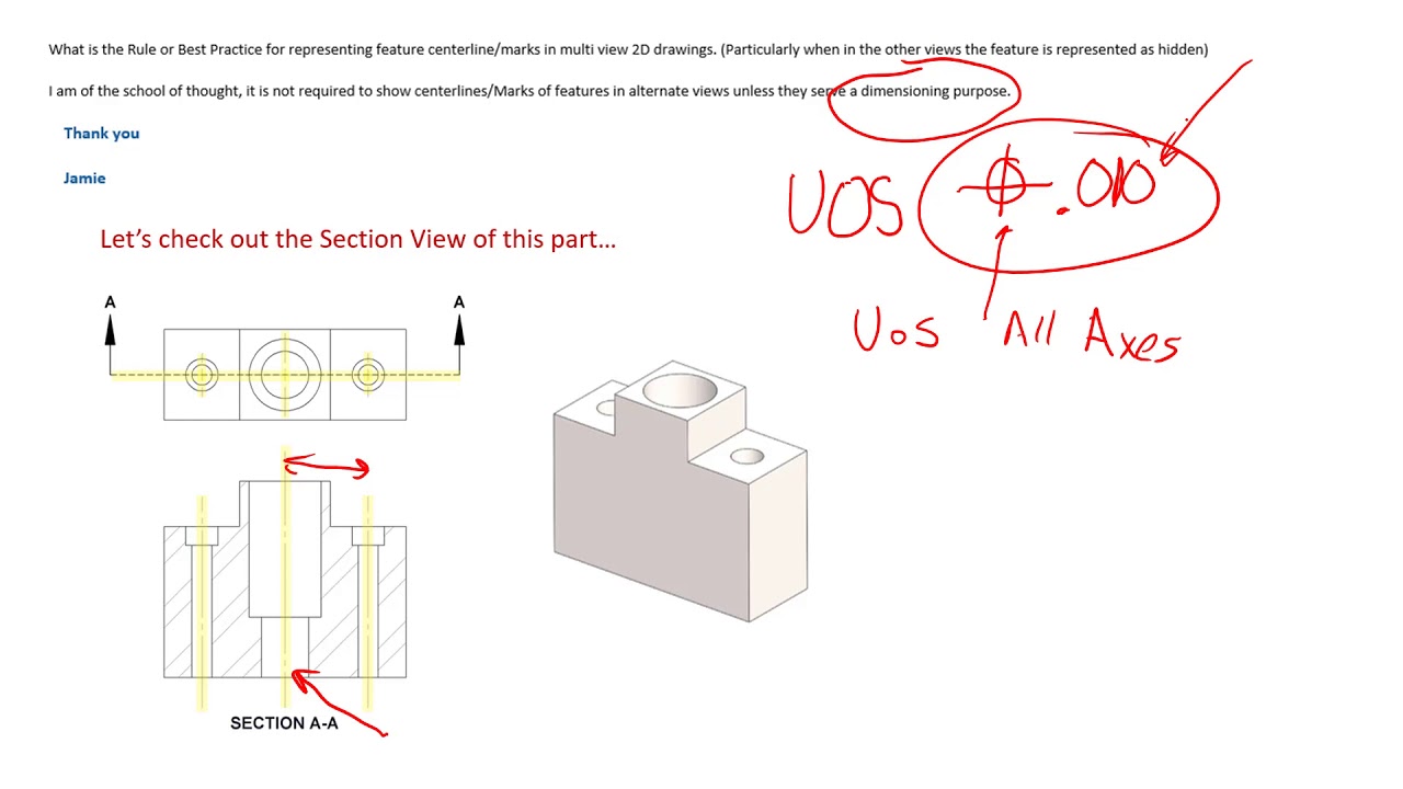
Centerlines on Engineering Drawings and how they should be used
Mechanical Drawing Lines Definition different line types used on engineering drawings. different line types used on engineering drawings. Certain features on a engineering drawing requires specific ways of. the diagonal lines on the section drawing are used to indicate the area that has been theoretically cut. / learn mechanical drawings / by piet. They are fine, dark lines. the most common is a continuous line, also known as a drawing line. In this comprehensive guide, we’ll delve into the diverse world of lines used in engineering drawings. lines in engineering drawing are more than just strokes on paper; section lines are used to show the cut surfaces of an object in section views. This post discusses the advantages of using the bs & iso standard line type definitions. lines on mechanical engineering drawings. Various types of section lines may indicate the. these lines are used to represent the outlines of adjacent parts, extreme positions of movable parts in the assembly drawings, parts. They convey critical information, dimensions, and details that guide the construction of complex structures, machinery, and systems.